Build Guide
Put the hardware together, start to finish: no soldering experience required.
This page walks through building your own Agent Andon Light, from installing the software you'll need to seeing the light turn on for the first time. If you've never soldered anything before, don't worry: the fabricated board only needs one part attached, and it's a lot more forgiving than it sounds.
Looking for the parts list instead? See the BOM.
1. Install the software
Before touching any hardware, install the tools that let your computer talk to the board:
- Install the Arduino IDE (version 2.x). This is the program you'll use to send the firmware (the small program that runs directly on the board) onto the device.
- Add support for this board's chip family:
- In the Arduino IDE, go to Preferences and add the
arduino-picoboard package URL under "Additional Board Manager URLs." - Open the Boards Manager and install "Raspberry Pi Pico/RP2040."
- When it's time to flash the firmware, select "Waveshare RP2040-Zero" as the board: that's the specific chip this device uses.
- In the Arduino IDE, go to Preferences and add the
- Install the Adafruit NeoPixel library (Tools → Manage Libraries → search "Adafruit NeoPixel" → Install). This is the library that knows how to talk to the LEDs: they need very precisely timed signals that a simple on/off command can't produce.
2. Build the hardware
If you don't have a board yet, start with fabricating one below, then come back and continue to If you have the fabricated board. If you already have one, or you're only testing without committing to a board yet, skip straight to whichever of the next two sections matches you: you only need one of those two.
If you want to fabricate your own board
Skip this if you already have the fabricated board, or you're only prototyping on a breadboard (see below).
Everything needed to have a real board made is in the hardware folder on GitHub:
- The KiCad project: the actual design files, in the same free tool (KiCad) used to design this board. Open it if you want to view or change the design yourself; skip it if you don't.
- The gerber files: a set of manufacturing files that tell a board fabrication service exactly what to build. You don't need to open or understand these: upload the whole folder to a fabrication service (this project used JLCPCB) and they send back a board with everything soldered on except the microcontroller, same as the parts list describes.
- The chassis files: ready-to-print files for the 3D-printed case, for a 3D-printing service or your own printer.
Once your board arrives, come back and continue below.
If you have the fabricated board
This is the easy path, and it's what most people will do. The fabricated board already has the LEDs and small components placed by the manufacturer: the only thing you need to attach yourself is the small microcontroller board (the RP2040-Zero, the chip that runs everything).
- Solder the RP2040-Zero onto the board. It has small half-circle notches along its edge (called "castellated pads") that line up with matching pads on the board. Solder each one. Some of these connections carry power and data, and some are just there to hold the chip in place mechanically, but it's simplest to just solder all of them.
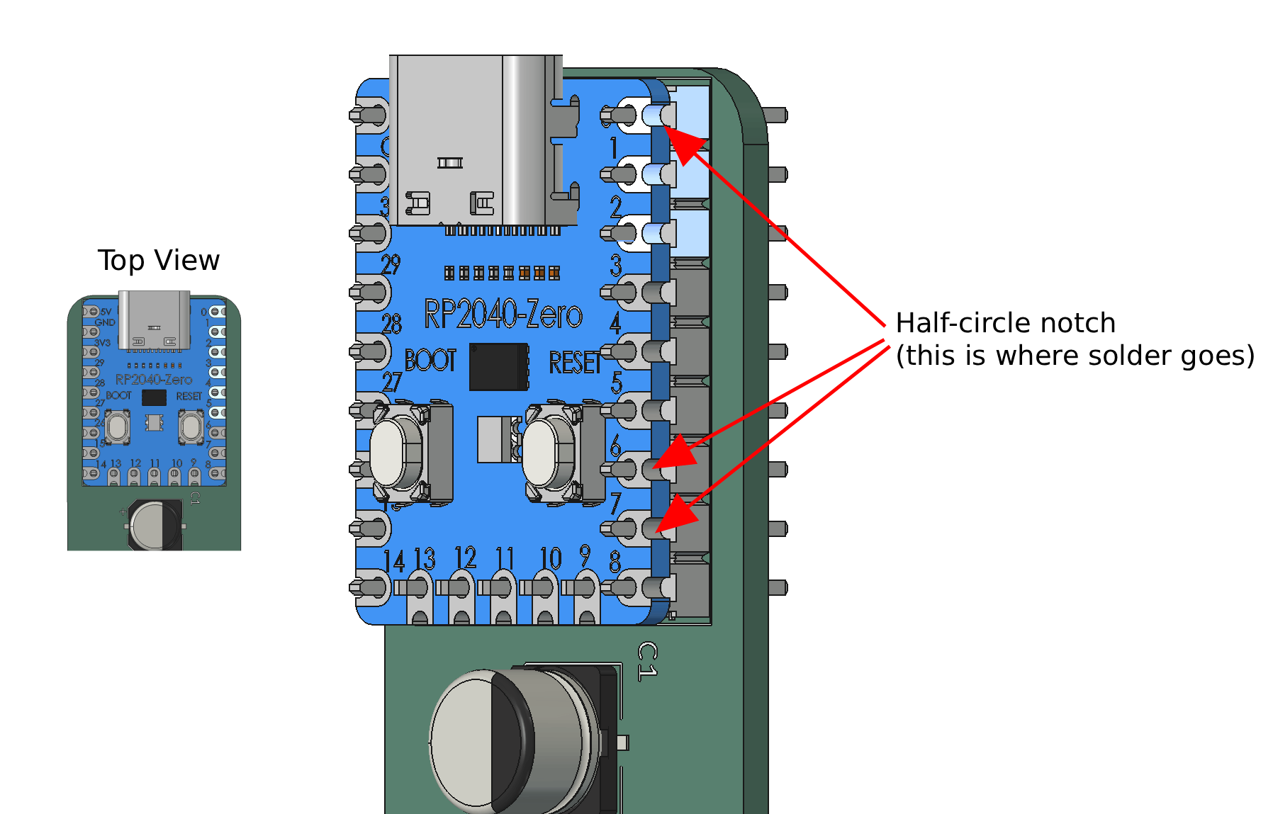
A couple of tips if you're new to soldering: let each joint cool for a few seconds before you touch it, and try not to let solder bridge across two neighboring pads into one blob. If that happens, you can usually fix it by reheating and adding a touch more solder to separate them, or using solder wick to pull the extra away.
That's the entire build: there's no cable to connect or wire to run. The connection between the chip and the LEDs is already built into the board itself. Once you're done soldering, skip ahead to Flash and verify.
If you're prototyping on a breadboard
Skip this section if you already did the fabricated-board build above. This path is for testing the firmware against a bare RP2040-Zero wired by hand to a separate LED strip, useful if you're experimenting before committing to the custom board, or don't have one yet.
-
Solder header pins onto the RP2040-Zero. It ships without any pins attached: just the bare half-circle notches. Solder on at least three: 5V, GND, and one GPIO pin (the firmware expects
GPIO1by default). Using a row of male header pins is the easiest way to go, since it lets the board plug into a breadboard like any other component. Soldering wires on directly works too, but it permanently commits you to those specific wires. -
Wire it to the LED strip:
 [RP2040-Zero]                    [LED strip, 3-pin connector]
   GND o---------------------------o G  (ground)
   5V  o---------------------------o V  (power, not 3V3, see below)
   GP1 o---------------------------o S  (signal / data)

   USB-C port -----> cable -----> your computer
A few things worth knowing:
- Connect the ground wire (
G) first. - Connect
Vto the5Vpin, not3V3. - Connect
S(signal) to whichever GPIO pin you soldered, matching thekDataPinsetting in the firmware file (or just edit that file to match however you wired it). - Plug in the USB-C cable only after all three wires are connected. Powering up a half-finished connection risks a short.
- Optional: a small resistor and capacitor can help with signal stability. See items #8–9 in the BOM if you run into flicker.
- Connect the ground wire (
The 3V3 pin can't supply enough current for 10 LEDs. Wiring V to 3V3 instead of 5V is the single most common wiring mistake people make on this build.
Once wired up, continue to Flash and verify.
3. Flash and verify
- Open
andon_light_firmware.ino(found underdevice/firmware/andon_light_firmware/in the project source) in the Arduino IDE. - Select "Waveshare RP2040-Zero" as the board, then click Upload to flash the firmware onto it.
- Open the Serial Monitor, set it to 115200 baud with the line ending set to "Newline."
- You should see the very first LED light up dim white, with the rest dark. That's the "I'm alive" indicator: it's always on, no matter what state the device is in.
- Type
G, thenY, thenRinto the Serial Monitor and press enter after each. Each one should light up its own group of three LEDs (positions 2-4, 5-7, and 8-10), not the whole strip.
If that all worked, congratulations. You have a working device. Next, install the host software so it can start following what your coding agent is doing: see the Quick Start on the project's GitHub page.
Reference
A few terms, explained
| Term | What it means |
|---|---|
| MCU (microcontroller) | The small chip that actually runs the firmware. On this board, that's the RP2040 inside the RP2040-Zero. |
| Firmware | The program that runs on the MCU itself. Not on your laptop. |
| Dev board | A ready-made small circuit board with the chip, USB port, and power handling already built in. The RP2040-Zero is one of these. |
| Addressable LED (WS2812) | An LED that can be told its own individual color over a single wire, even when many are chained together. That's what lets each 3-LED group show a different color independently. |
| NeoPixel | Adafruit's name for this LED family, and for the library that drives them. |
| Watchdog | A safety timer in the firmware that resets the light to a "something's wrong" state if it hasn't heard from your computer in a while. See the wire protocol reference below. |
| PCBA | Short for "PCB assembly": a circuit board with all its components already soldered on. |
How the LEDs are laid out
| LEDs | Meaning | Turned on by |
|---|---|---|
| 1 | Always-on "I'm alive" light | Nothing: it's just always dim white |
| 2–4 | Working | The G command |
| 5–7 | Waiting on you | The Y command |
| 8–10 | Idle | The R command, or a stale connection |
| State | What you'll see |
|---|---|
Working (G) | LEDs 2-4 solid green |
Waiting (Y) | LEDs 5-7 solid yellow |
Idle (R) | LEDs 8-10 solid red |
| Stale connection | LEDs 8-10 slowly pulsing red, instead of solid |
Compacting (C) | A chase pattern: lights fill in one at a time from LED 10 down to LED 2, then reset and repeat |
LED 1 stays dim white through all of this, right from the moment the device powers on. If you ever see all 10 LEDs light up the same color at once, that means older firmware is flashed: re-flash from the current source.
Common pitfalls
| What you might see | What's going on |
|---|---|
V wired to 3V3 instead of 5V | Breadboard build only. This is the single most common mistake: 10 LEDs need more current than 3V3 is meant to provide. |
| Flickering or wrong colors right after power-up | Usually a shaky connection, not a bug in the firmware. On the fabricated board, check for a cold solder joint. On a breadboard, see the troubleshooting page's note on signal issues. |
| Wrong wire in the wrong hole | Breadboard build only. Read the tiny labels printed on the LED strip's connector itself rather than trusting a photo or this guide. Always double check against what's actually printed on your board. |
| Nothing happens over USB | Some USB-C cables only carry power, not data. Try a different cable before anything else. |
| Skipping the Serial Monitor check | It's worth doing even though it feels like an extra step: it tells you whether a problem is in the firmware or in the software on your computer, before you add another layer on top. |
| The light seems stuck / not updating | The Claude Code integration only checks in at specific moments, not continuously: a long stretch of pure thinking with no tool calls can leave the watchdog momentarily unfed. This is expected and resolves itself; see the wire protocol table above. |
The watchdog and heartbeat aren't just a nice-to-have: they're what makes it safe to actually walk away and trust the light while you're gone.
Notes for your operating system
| OS | What to expect |
|---|---|
| Windows | Shows up as a COM port automatically, no extra driver needed. |
| Linux | Shows up as /dev/ttyACM0 (or similar). Your user account needs to be in the dialout group to access it. See the troubleshooting page if you hit a permission error. |
Wire protocol reference
This is the exact set of single-character commands the computer sends to the device over USB:
| Command | Effect | Meaning |
|---|---|---|
G | Solid green | Agent is working |
Y | Solid yellow | Waiting on you for input or a permission |
R | Solid red | Idle, stopped, or a new session just started |
C | Chase pattern | Housekeeping ("compacting"): the agent is still alive, just tidying up |
H | No visual change | A heartbeat: just resets the watchdog timer |
If the device doesn't hear from your computer for 30 minutes, it assumes something went wrong and switches to the slow pulsing red pattern rather than freezing on whatever color it last showed.